
LOADING
- Many communication interfaces, including M.2
- Reference design for custom carrier boards
- Included in iMX Developer's Kit V2
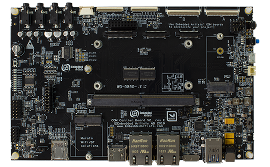
The COM Carrier board is a reference design for custom carrier boards using Embedded Artists COM boards.
Updated Carrier board design – V2
This is the second generation reference design with several enhancements of features and usability:
- Support for i.MX8 designs
- Support for M.2 Key E interface (typically Wi-Fi/BT), including advanced debug features developed in cooperation with Murata and Cypress
- Support for M.2 Key B interface (typically Cellular/SSD)
- Support for USB 3.0
- Updated power supply design
- Direct support for New Haven LVDS display
- Access to all audio codec interfaces
- Expansion board for easy prototyping
Many RF solutions
The on-board connectors such as M.2 (both E-key and B-key), SDIO, XBee makes it simple to add RF solutions. Our family of Wi-Fi/BT M.2 modules (based on Murata modules) are directly supported.
Display solutions
It is easy to add a display to the carrier board using the COM Display Adapter. See the page Display Solutions for COM boards for more details about how to add a display.
Supported COM boards
The COM Carrier Board is compatible with the following COM boards:
| Connectors and interfaces | |
|---|---|
| MXM3, 314-pos connector with standoffs for COM boards | |
| Dual 10/100/1000 Mbps Ethernet RJ45 connectors | |
| USB 3.0 OTG interface | |
| Dual USB 3.0 Host interfaces (via USB 3.0 Hub) | |
| HDMI connector | |
| UART-to-USB bridge for console connection | |
| uSD connector | |
| Audio codec with line out, line in, mic in and headphone out via 3.5mm audio jack connectors | |
| M.2 E-key connector (with SDIO, PCIe and USB interfaces connected) - for Wi-Fi/BT M.2 modules | |
| M.2 B-key connector (with USB, SIM card holder and SATA interfaces connected) | |
| Dual LVDS connectors, connects directly to a New Haven NHD-10.1-1024600AF-LSXV-CTP display | |
| FPC connectors for serial camera interface (MIPI-CSI), parallel camera interface and serial display output (MIPI-DSI) | |
| Parallel RGB display interface connector | |
| Dual 50-pos FPC expansion connectors (to access many COM Board signals) | |
| Power | |
|---|---|
| 12V (+-30%) supply voltage, with reverse polarity protection | |
| DC/DC converter: 3.3 or 4.2V/4A for COM board powering | |
| DC/DC converter: 3.3V/3A and 5V/3A for carrier board powering | |
| DC/DC converter: 3.3 or 3.6V/3A for M.2 Wi-Fi/BT powering | |
| Li-Ion / Li-Polymer battery charger for COM board RTC (note: battery not included) | |
| Dimensions | |
|---|---|
| 201 x 126 mm | |
| Five 4.3mm holes for mounting and grounding | |
| Expansion board | |
|---|---|
| XBee™ compatible interface connector | |
| Click board connector | |
| PRi expansion connector | |
| Arduino shield compatible connector | |
| Dual CAN transceivers with ESD protection and optional termination | |
| I2C temperature sensor | |
| I2C light sensor | |
| Access to all expansion signals | |
| Other | |
|---|---|
| On/Off and Reset pushbuttons | |
| Input and COM board current measurement | |
| Real-Time Clock with supercap backup | |
| Environment | |
|---|---|
| 0 - 60° Celsius | |
| 5 - 90% relative humidity, non-condensing | |
| Product Classification | |
|---|---|
| Evaluation board | |
* Note: the used COM board must support the specific interface to make use of the carrier board interfaces/connectors.
| Flyers and specifications | |
|---|---|
| COM Carrier Board V2 Datasheet | |
| COM Carrier Board Schematics | |
| Expansion Board Pinning | |
| Conformity | |
|---|---|
| Product compliance declarations | |