
LOADING
- Two-board solution (LPC1769 + LPC11C24)
- Onboard CAN network
- Several communication interfaces
The AOAA Kit is a standalone platform for evaluation and prototyping electronic accessories for Google’s Android operating system
Note: The AOA protocol implementation is quite old and may not work with newer Android devices. No support is given on the AOA implementation. This is however still a nice communication platform.
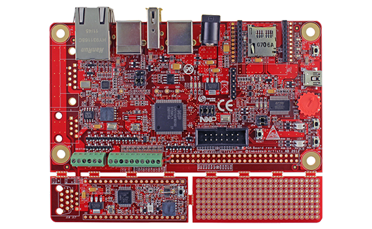
The AOAA Kit is a standalone platform for evaluation and prototyping electronic accessories for Google’s Android operating system. It lets you get up-and-running with AOA experiments immediately. The AOAA board is also suitable for experimenting with CAN, Ethernet and RF networks.
The board has been developed by Embedded Artists in close cooperation with NXP. It contains two microcontrollers from NXP, the LPC1769(Cortex-M3 core) and LPC11C24(Cortex-M0 core). The two microcontrollers are connected via an on-board CAN network.
Easy usage
Download code to the board by using:
- ISP over UART program download. Use the free tool Flash Magic to download a compiled application to the LPC1769 side of the AOAA board. Please note that this tool cannot be used to download code to the LPC11C24 side of the board.
- Use the free MCUXpresso IDE together with LPC-Link2
- Alternativelt, use a debugger and JTAG adapter of your choice that supports the Cortex-M3 and Cortex-M0 ARM cores and more specifically the NXP LPC1769 and LPC11C24 microcontrollers. You might need an adapter such as the 10-pin to 20-pin JTAG Adpater Kit between your JTAG solution and the target board.
| AOAA Board (LPC1769) |
|---|
| Processor | |
|---|---|
| NXP's Cortex-M3 LPC1769 microcontroller in 100-LQFP package | |
| 512 KByte flash | |
| 64 KByte RAM | |
| USB | |
|---|---|
| USB Host interface for Android connection | |
| USB Device interface (future proof for when Android devices can be USB Hosts also) | |
| Communication interfaces | |
|---|---|
| 100/10M Ethernet interface based on SMSC LAN8720 Ethernet PHY | |
| CAN interface (DSUB9 and RJ45 connector pads exist, not mounted per default) | |
| Pads for interfacing NXP/Jennic RF module (JN5148-XXX-M00) | |
| Socket for Digi™ XBee RF module and interface compatible modules | |
| Serial Expansion Connector, 14-pos connector with UART/I2C/SPI/GPIO pins | |
| Power and dimensions | |
|---|---|
| Powered via Android device’s normal USB power plu | |
| +5V DC external supply can also be connected via standard 2.1mm power jack | |
| Internal +3.3V powering on board | |
| 135x100 mm (total size of board) | |
| IO and Peripherals | |
|---|---|
| Two RGB LEDs | |
| Two push buttons | |
| Analog input with trimming potentiometer | |
| Eight protected inputs/outputs (of which four can be analog inputs) | |
| Four open collector outputs (for driving for example relays) | |
| All free LPC1769 pins available on expansion connector | |
| UART-to-USB bridge that also supports automatic ISP (for program download via UART/USB) | |
| SWD/JTAG connector, 2x5 pos, 50 mil/1.27 mm pitch, standard SWD/JTAG connector | |
| CAN Node (LPC11C24 side) |
|---|
| Processor | |
|---|---|
| NXP's Cortex-M0 LPC11C24 microcontroller in 48-LQFP package | |
| 32 KByte flash | |
| 8 KByte RAM | |
| CAN interface | |
|---|---|
| Directly connected to LPC1769 CAN interface on same board | |
| Pads for DSUB9 and RJ45 CAN interface connectors exists (connectors not mounted) | |
| Power and dimensions | |
|---|---|
| Powered via CAN interface (+5V) | |
| On-board +3.3V powering | |
| 69 x 23 mm (part of the big 135 x 100 mm board) | |
| Connector | |
|---|---|
| All relevant LPC11C24 pins available on expansion connectors (dual 20 pos edge connector, 100 mil/2.54 mm pitch rows, 700 mil apart) | |
| SWD/JTAG connector, 2x5 pos, 50 mil/1.27 mm pitch, standard SWD/JTAG connector | |
| Other | |
|---|---|
| RGB-LED | |
| LED on PIO0_7 (compatible with LPCXpresso LPC11C24 board design) | |
| Push-button on wakeup pin (PIO1_4), allowing low-power experiments | |
| LM75 temperature sensor on I2C | |
| ISL29003 light sensor on I2C | |
| Product Classification and Status | |
|---|---|
| Evaluation board | |
| Flyers and specifications | |
|---|---|
| AOAA Kit User's Guide | |
| AOAA Board measurements | |
| AOAA Board Schematics | |
| Documentation and guides | |
|---|---|
| AOAA Kit Software User's Guide | |