
LOADING
- NXP's Cortex-M0 LPC12D27
- LCD with 8 14-segment characters
- All LPC12D27 pins are available on connectors
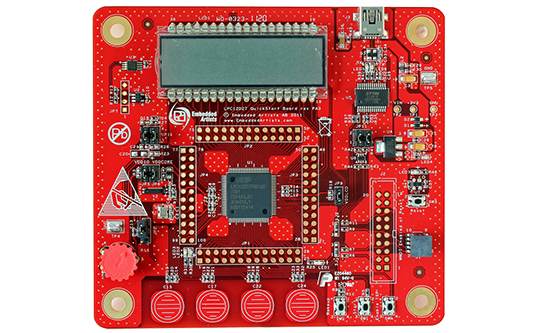
The LPC12D27 QuickStart Board lets you get up-and-running quickly with NXP's Cortex-M0 LPC12D27 microcontroller.
| Processor | |
|---|---|
| NXP's Cortex-M0 LPC12D27 microcontroller in 100-pin LQFP package. | |
| 128 KByte flash. | |
| 8 KByte RAM | |
| Clock crystals | |
|---|---|
| 12.000 MHz external crystal. The LPC12D27 runs at frequencies up to 45 MHz. | |
| 32.768 kHz rtc crystal. | |
| Interfaces / Connectors | |
|---|---|
| All LPC12D27 pins are available on expansion connectors around the processor (100 mil/2.54 mm pitch dual rows). | |
| UART-to-USB bridge interface for LPC12D27 UART, with mini-B USB connector and proper ESD protection. | |
| mini-B USB connector. | |
| SWD/JTAG connector (50 mil/1.27 mm pitch, standard SWD/JTAG connector). Pad for older, larger 20pos 100 mil pitch JTAG connector also exists, but connector not soldered. | |
| Power | |
|---|---|
| Flexible powering, with on-board 800mA 3.3V voltage regulator. Can be powered from USB connector, JTAG connector (if supported by JTAG device) or an external +5V supply. | |
| Other | |
|---|---|
| LCD with 8 14-segment characters. | |
| 32 Kbit I2C E2PROM. | |
| LM75 I2C temperature sensor. | |
| Trimming potentiometer on analog input. | |
| 4 capacitive sensors. | |
| Support for '555' hardware timer functionality of the LPC12D27. | |
| Onboard reset generation and reset push-button. | |
| Push-button for enabling Bootloader mode of the LPC12D27. | |
| Push-button for enabling start logic of the LPC12D27. | |
| Push-button for wakeup logic of the LPC12D27. | |
| Possibility to measure current consumption for LPC12D27 core, I/O and LCD controller parts individually. | |
| 3 LED on pin PIO0_12, PIO0_27 and PIO0_28. | |
| Flyers and specifications | |
|---|---|
| LPC12D27 QuickStart Board schematics | |
| Documentation and guides | |
|---|---|
| LPC12D27 QuickStart Board User's Guide | |
| Software resources | |
|---|---|
| lpc12d27_qsb_111101.zip | |