
LOADING
- Many communication interfaces, including M.2
- Reference design for custom carrier boards
- Included in iMX uCOM Developer's Kit
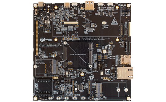
The uCOM Carrier board is a reference design for custom carrier boards using Embedded Artists uCOM boards.
uCOM Carrier board design
This is a new reference design specifically for our uCOM boards, with several enhancements of features and usability:
- Support for i.MX RT1176, RT1166 and RT1064 uCOM designs
- Support for i.MX8M Mini/Nano uCOM designs
- Support for M.2 Key E interface (typically Wi-Fi/BT)
- Support for M.2 Key B interface (typically Cellular)
- MIPI-DSI to HDMI bridge adapter
- Expansion connector for easy prototyping
Many RF solutions
The on-board connectors such as M.2 (both E-key and B-key) and uSD makes it simple to add RF solutions. Our family of Wi-Fi/BT M.2 modules (based on Murata modules) are directly supported.
Supported uCOM boards
The uCOM Carrier Board is compatible with the following uCOM boards:
Note that all interfaces/connectors are not available for all uCOM boards. It depends on what interfaces the used processor supports. Check the respective uCOM datasheet for details.
| Connectors and interfaces | |
|---|---|
| Hirose DF40C 100/40-pos connectors with standoffs for uCOM board | |
| M.2 E-key connector (with SDIO, PCIe and USB interfaces connected) - for Wi-Fi/BT M.2 modules | |
| M.2 B-key connector (with PCIe, USB and SIM card holder interfaces connected) | |
| 1000/100/10 Mbps Ethernet RJ45 connector | |
| USB OTG interface | |
| USB Host interface | |
| uSD memory card connector | |
| Dual UART-to-USB FTDI bridges for console connections | |
| Display interface (MIPI-DSI), dual connectors | |
| Display interface (parallel RGB) with backlight control. Note: LCD not included in all Developer's Kits. | |
| Camera interface (MIPI-CSI) | |
| Debug interface with 2x5 pos 50 mil pitch Cortex debug connector | |
| Mikrobus interface connector for Click boards™ | |
| Expansion connectors for accessing uCOM board signals | |
| Power | |
|---|---|
| 12V (+-30%) supply voltage, with reverse polarity protection | |
| External VBAT power input (for uCOM RTC) | |
| Current measurement possibilities in supply voltages | |
| 5V/3A DC/DC supply to uCOM | |
| 3.3V/3A DC/DC supply to RF modules (M.2 interface connectors), exist on uCOM Carrier Boards, rev PB2 | |
| Dimensions | |
|---|---|
| 152 x 152 mm | |
| Five 4.3mm holes for mounting and grounding | |
| Other | |
|---|---|
| USB Hub | |
| On/Off, Reset, ISP Enable, Wakeup and user push-buttons | |
| RGB-LED, LEDs, I2C-GPIOs and I2C-PWMs | |
| Pads for mounting QSPI flash memories | |
| Adapter for second 100/10 Mbps Ethernet PHY | |
| Adapter for MIPI-DSI to HDMI | |
| Environment | |
|---|---|
| 0 - 60° Celsius | |
| 5 - 90% relative humidity, non-condensing | |
| Product Classification | |
|---|---|
| Evaluation board | |
* Note: the used uCOM board must support the specific interface to make use of the uCOM Carrier board interfaces/connectors.
| Documentation and guides | |
|---|---|
| uCOM Carrier board schematics | |
| Conformity | |
|---|---|
| Product compliance declarations | |