LOADING
- Evaluate the LPC1788 OEM board
- All relevant interfaces are available
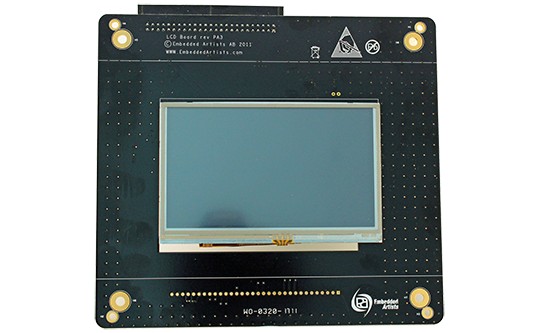
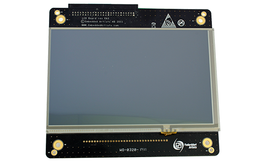
- Easy to add display options
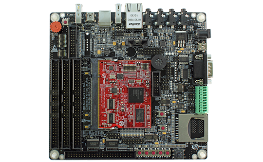
The LPC1788 Developer's Kit lets you get up-and-running quickly with the LPC1788 OEM Board. All relevant interfaces are available for evaluation or prototyping.
What is included when buying a kit?
- LPC1788 OEM board
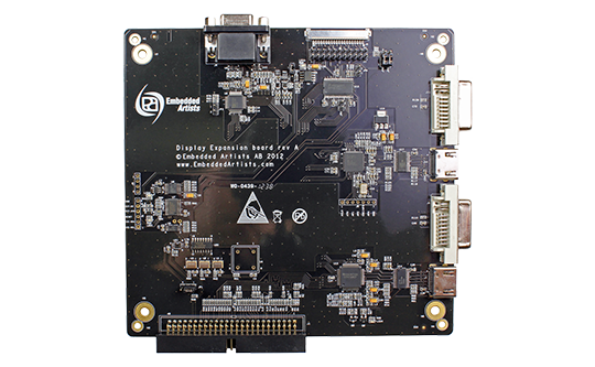
- OEM Base board
- One mini-B to A USB Cable
- Headset with microphone
External resources
- Blunk’s CrossStep IDE with Getting started manual
- Blunk $5K RTOS bundle
- uTrace setup guide for Lauterbach
- Segger’s evaulation software package.
- NXP’s emWin package.
| Connectors and interfaces | |
|---|---|
| 200 pos, 0.6mm pitch SODIMM connector for OEM Board | |
| LCD expansion connector with control signals for touch screen interface | |
| Expansion connector with all OEM Board signals | |
| Ethernet connector (RJ45) | |
| CAN interface & connector (provision for second CAN interface, but not mounted) | |
| MMC/SD interface & connector | |
| USB1: OTG or Host interface & connector | |
| USB2: Device or Host interface & connector | |
| Provision for NXP JN5148 RF module (former Jennic) interface (RF module not included) | |
| Full modem RS232 (cannot be fully used on 32-bit databus OEM boards) | |
| RS422/485 interface & connector | |
| Provision for IrDA transceiver interface (transceiver not mounted) | |
| I2S audio codec (mic in, line in, line out, headphone out) | |
| SWD/JTAG connector | |
| Trace connector and pads for ETM connector | |
| Serial Expansion Connector, 14-pos connector with UART/I2C/SPI/GPIO pins | |
| Power | |
|---|---|
| Power supply, either via USB or external 5V DC | |
| Optional coin cell battery for RTC and LED on ALARM output (coin cell not included) | |
| Other | |
|---|---|
| OEM Board current measuring | |
| Parallel NOR flash on external memory bus | |
| 16-bit register and LEDs on external memory bus | |
| 5-key joystick | |
| LM75 temperature sensor (I2C connected) | |
| 5 push-button keys (four via I2C and one on ISP-ENABLE) | |
| 9 LEDs (8 via I2C and one on ISP-ENABLE) | |
| Trimming potentiometer to analog input | |
| USB-to-serial bridge on UART #0 (FT232R) and ISP functionality | |
| Reset push-button and LED | |
| Speaker output on analog output from OEM Board, or from I2S audio codec | |
| 160x150 mm in size | |
| Product Classification | |
|---|---|
| Evaluation board | |
Note: Specifications for the OEM board is available on the LPC1788 OEM board page.
| Flyers and specifications | |
|---|---|
| LPC1788 Developer's Kit User's Manual | |
| OEM Baseboard Schematics | |
| OEM Baseboard Component Placement | |
| Documentation and guides | |
|---|---|
| OEM Board Integration Guide | |
| Product notes / changes | |
|---|---|
| NAND change and Measurements (2015-01-21) | |
| Software resources | |
|---|---|
| lpc1788_samples_150612.zip | |
| lpc1788_binaries_150603.zip | |