
LOADING
- Many communication interfaces, including M.2
- Reference design for custom carrier boards
- Included in SOM Developer's Kit
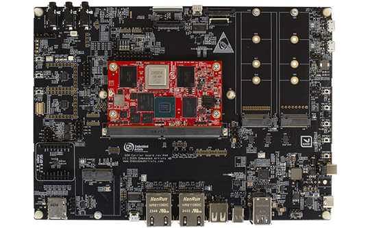
The SOM Carrier board is a reference design for custom carrier boards using Embedded Artists SOM boards.
SOM Carrier board design
This is a new reference design specifically for our SOM boards, with several enhancements of features and usability:
- Support for RZ/G3E SOM designs
- Support for i.MX8M Mini SOM designs
- Support for M.2 Key E interface (typically Wi-Fi/BT)
- Support for M.2 Key M interface (typically SSD)
- Support for M.2 Key B interface (typically Cellular)
- On-board MIPI-DSI to HDMI bridge
Many RF solutions
The on-board connectors such as M.2 (both E-key and B-key) and uSD makes it simple to add RF solutions. Our family of Wi-Fi/BT M.2 modules (based on Murata modules) are directly supported.
Supported SOM boards
The SOM Carrier Board is compatible with the following SOM boards:
Note that all interfaces/connectors are not available for all SOM boards. It depends on what interfaces the processor in use supports. Check the respective SOM datasheet for details.
| Connectors and interfaces | |
|---|---|
| MXM3, 314-pos connector with standoffs for SOM boards | |
| M.2 E-key connector (with SDIO, PCIe and USB2 interfaces connected) - for Wi-Fi/BT M.2 modules | |
| M.2 B-key connector (with PCIe, USB2 and SIM card holder interfaces connected) | |
| M.2 M-key connector (with PCIe and USB2 interfaces connected) | |
| Dual 1000/100/10 Mbps Ethernet RJ45 connector | |
| USB 3.0 OTG interface | |
| USB3 Hub with Dual USB3 Host interfaces | |
| USB2 Host interface | |
| uSD memory card connector | |
| Dual UART-to-USB FTDI bridges for console connections | |
| MIPI-DSI display interface via FPC or via MIPI-DSI to HDMI bridge | |
| Parallel RGB display interface connector with backlight control. Note: LCD not included in Developer's Kits. | |
| HDMI connector | |
| Dual MIPI-CSI camera interfaces | |
| Dual CAN interfaces | |
| Real-Time Clock (PCF8523TK/1) | |
| Audio code (DA7212-01UM) with stereo Microphone input, Line input, Headphone output and Speaker output (speaker not included). | |
| Infineon OPTIGA Trust M secure element (SLS32AIA010MK) | |
| NXP SE050 secure element (SE050C1HQ1) | |
| Power | |
|---|---|
| 12V (+-30%), 2.5A supply voltage, with reverse polarity protection | |
| USB-C connector for USB-PD power supply (12V / 3A required) | |
| External VBAT power input (for RTC) | |
| Current measurement possibilities in supply voltages | |
| 5V/5A DC/DC supply to SOM and USB interfaces | |
| 3.3V/3A DC/DC supply to M.2-E interface connector (RF modules) | |
| 3.3V/3A DC/DC supply to M.2-B and M.2-M interface connectors | |
| Dimensions | |
|---|---|
| 162 x 235 mm | |
| Six 4.3mm holes for mounting and grounding | |
| Other | |
|---|---|
| On/Off, Reset, ISP Enable, Wakeup and three user push-buttons | |
| RGB-LED, LEDs and I2C-GPIOs | |
| Debug interface with 2x5 pos 50 mil pitch Cortex debug connector | |
| Mikrobus interface connector for Click boards™ | |
| Expansion connectors for accessing SOM board signals | |
| Environment | |
|---|---|
| 0 - 50° Celsius | |
| 5 - 90% relative humidity, non-condensing | |
| Product Classification | |
|---|---|
| Evaluation board | |
* Note: the used SOM board must support the specific interface to make use of the SOM Carrier board interfaces/connectors.
| Flyers and specifications | |
|---|---|
| Default jumpers for SOM Carrier Board with iMX8M Mini | |
| Default jumpers for SOM Carrier Board with RZ-G3E | |
| Documentation and guides | |
|---|---|
| SOM Carrier Board schematic | |
| Conformity | |
|---|---|
| Product compliance declarations | |