
LOADING
- ARM7TDMI LPC2129
- Dual CAN channels
- Dual 2x16 pins I/O connectors
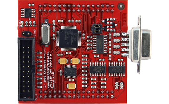
The LPC2129 CAN QuickStart Board lets you get up-and-running quickly with NXP's ARM7TDMI LPC2129 microcontroller
| Processor | |
|---|---|
| NXP's ARM7TDMI LPC2129 microcontroller | |
| 256 KByte flash | |
| 16 KByte RAM | |
| Power | |
|---|---|
| On-board low-dropout voltage and reset generation | |
| Generates +3.3V and +1.8V from a +5V supply | |
| +3.3V available for external circuits, up to 300 mA | |
| Power supply: 5 VDC | |
| Interfaces / Connectors | |
|---|---|
| Dual CAN channels with TJA1040 or TJA1041 transceivers | |
| Dual 2x16 pins I/O connectors | |
| All LPC2129 I/O pins are available on connectors | |
| RS232, DSUB-9 (ESD/EMI protected) | |
| Other | |
|---|---|
| 256 Kbit I2C E2PROM | |
| Simple and automatic program download (ISP) via serial channel. Circuit that automatically controls the bootloader from RS232 channel | |
| Four layer PCB (FR-4 material) for best noise immunity | |
| Easy to connect to JTAG signals | |
| Crystal: 12.0000 MHz crystal for maximum execution speed and standard CAN bit rates (5 x PLL = 60 Mhz CPU clock) | |
| Dimensions: 58 x 55 mm | |
| Flyers and specifications | |
|---|---|
| LPC2106 QSB Schematics | |
| Documentation and guides | |
|---|---|
| LPC2129 CAN QuickStart Board User's Guide | |
| Software resources | |
|---|---|
| LPC2xxx_QSB_sample_applications.zip | |